
电动无人巴士的制动系统设计(含CAD零件装配图,CATIA三维图)
电动无人巴士的制动系统设计(含CAD零件装配图,CATIA三维图)(任务书,开题报告,文献摘要,外文翻译,论文说明书11000字,CAD图11张,CATIA三维图)
摘 要
随着汽车工业的发展,汽车作为当前普通民众能够接触到的包含最多科技的产品综合体,其发展也越来越趋向于网联化、无人化、轻量化、电动化。为了适应这些变化,汽车的硬件系统需要有与之相应的匹配和优化。制动系统对于汽车安全行驶的重要性毋庸置疑,制动系统性能的优良与否对于整车性能有着巨大的影响,性能良好的制动系统能够给予车内乘员生理、心理上双重保护。
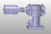
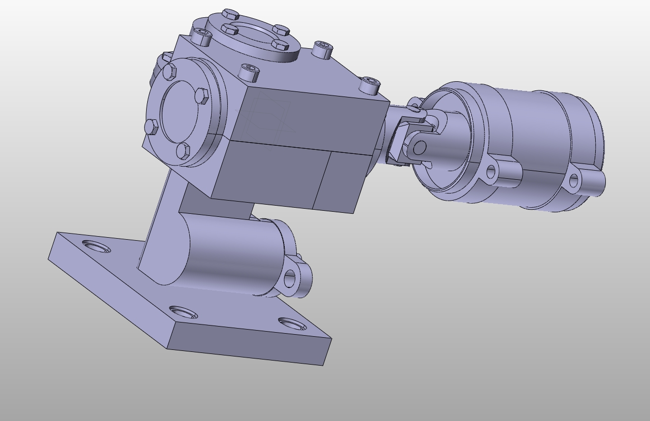
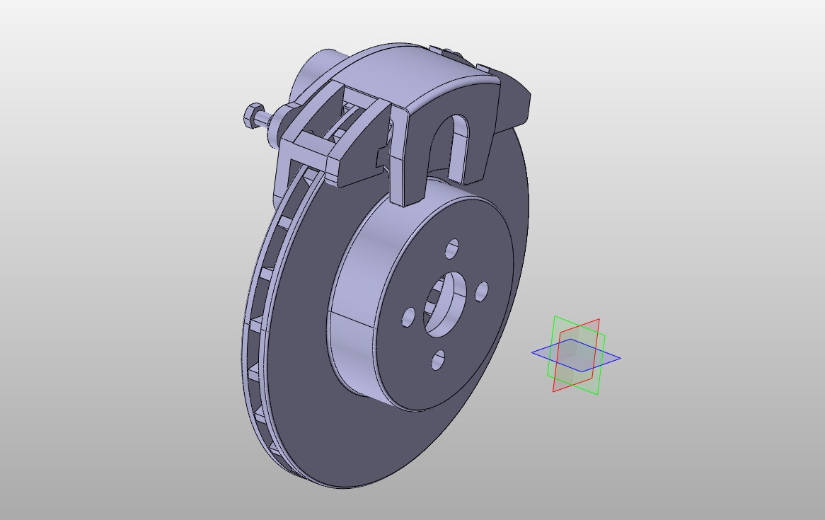
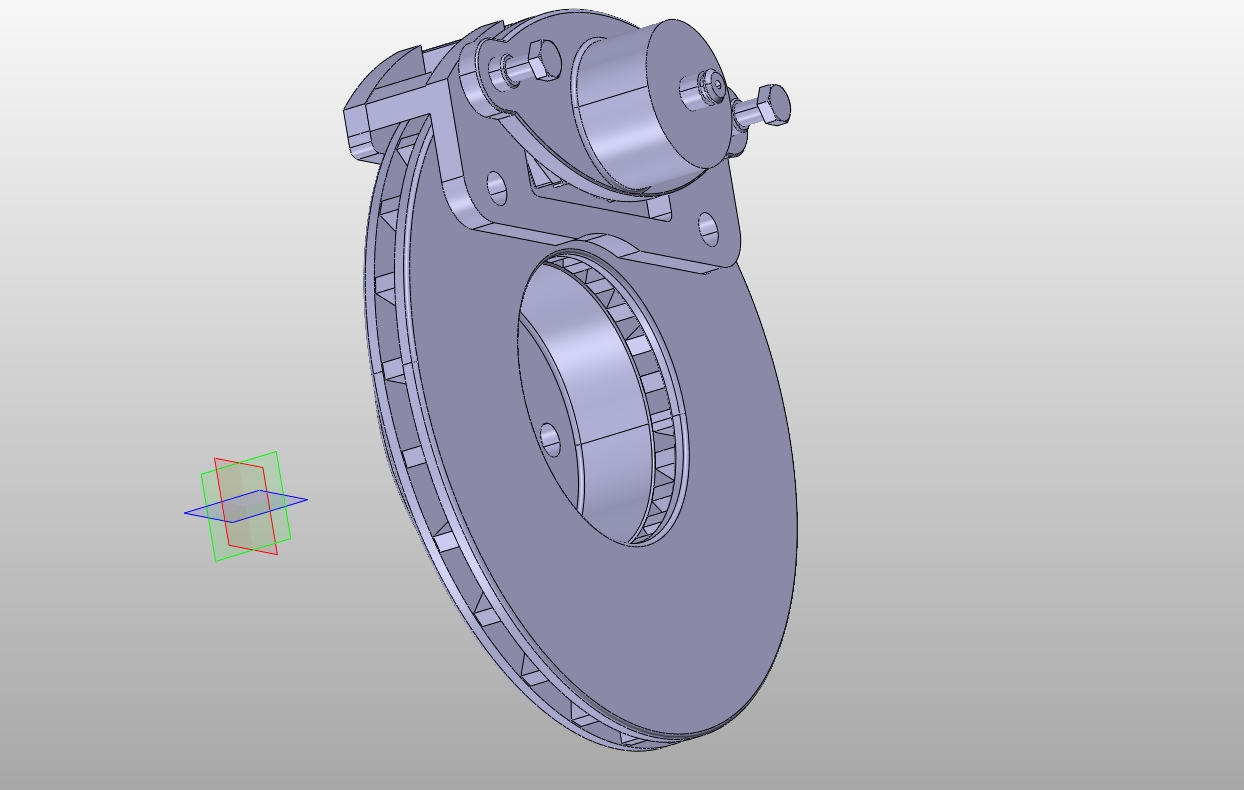
本文在综合考虑了汽车电动化与无人化后的制动系统面临的诸多问题针对一款无人电动巴士设计了一种电控制动系统,其基本原理是利用伺服电机推动制动主缸建压制动,通过控制电机转动的时间、角度就能够控制制动强度与制动时间,适用于无人驾驶汽车。本文通过matlab、cad、catia等软件对其制动系进行设计、选型、优化。首先比较各制动器的优缺点选择了制动器的类型,然后根据整车基本参数,通过国家法规对制动距离的要求得出制度减速度,以此作为依据计算制动器需要的制动力矩,从而可计算出制动器的基本结构参数,接着对制动器的各性能指标作校核。针对无人驾驶车辆的制动驱动机构进行了设计、选型、优化,接着根据前述计算参数计算制动主缸、轮缸的尺寸以及对制动驱动机构及其相应减速机构作选型与计算。设计的电控制动系统基本满足无人驾驶电动车对制动系统的需求。 [资料来源:http://Doc163.com]
关键词:无人驾驶;电动巴士;制动系统。
Abstract
With the development of the automobile industry, automobiles, as a product complex containing the most scientific and technological elements that the general public can now reach, are increasingly becoming more and more networked, unmanned, lightweight, and electrified. In order to adapt to these changes, the car's hardware system needs to be matched and optimized accordingly. The importance of the braking system for safe driving of the vehicle is undoubted. The performance of the braking system has a great influence on the performance of the vehicle. A good braking system can give the occupants both physiological and psychological protection.
After comprehensive consideration of many problems faced by the motorized and unmanned brake systems of the vehicle, this article has designed an electric control dynamic system for an unmanned electric bus. The basic principle is to use a servo motor to propel the brake master. The cylinder builds a pressure brake, which can control the braking intensity and braking time by controlling the time and angle of motor rotation. It is suitable for driverless cars. This article through the matlab, cad, catia and other software on its brake system design, selection, optimization. First, compare the advantages and disadvantages of each brake, select the type of brake, and then according to the basic parameters of the vehicle, obtain the system deceleration through the requirements of the national regulations on the braking distance, and calculate the braking torque required by the brake as a basis to calculate The basic structural parameters of the brake. Then check the performance of the brake. The design, selection and optimization of the brake drive mechanism of the unmanned vehicle are performed. Then, the size of the master cylinder and the wheel cylinder is calculated based on the aforementioned calculation parameters, and the brake drive mechanism and its corresponding reduction mechanism are selected and calculated. . The designed electric control system basically meets the demand of the unmanned electric vehicle for the braking system. [资料来源:Doc163.com]
Key Words:unmanned driving; electric bus;braking syst


 [来源:http://Doc163.com]
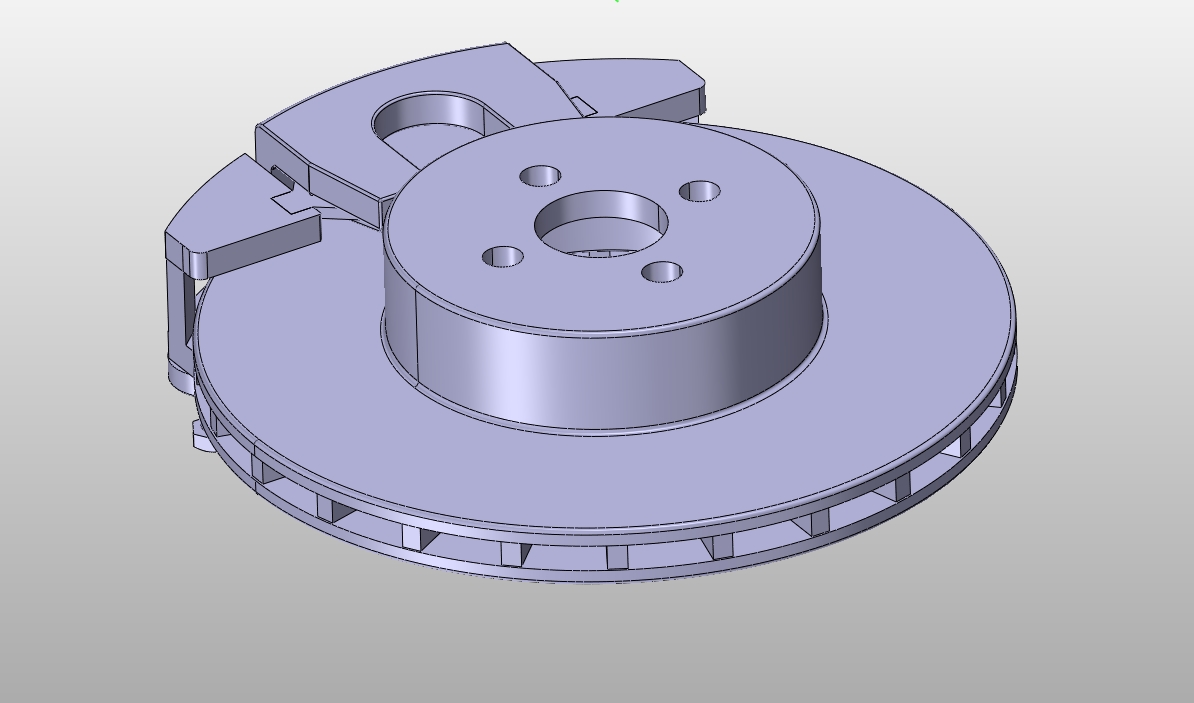
 [来源:http://www.doc163.com]


目录
[资料来源:http://Doc163.com]
第1章 绪论 1
1.1研究背景及意义 1
1.2国内外研究现状 1
1.3课题研究内容 2
1.4预期目标成果 2
第2章 总体方案确定 3
2.1无人驾驶制动功能的实现 3
2.1.1加装驱动机构 3
2.1.2电控液压制动系统(EHB) 3
2.1.3电控机械制动系统(EMB) 3
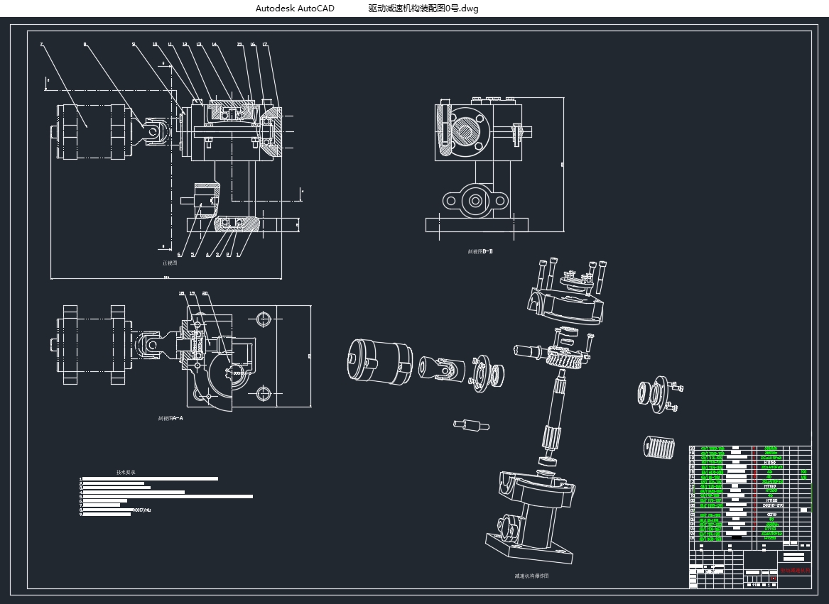
2.2 制动系统驱动减速机构 4
2.3 制动回路的选择 5
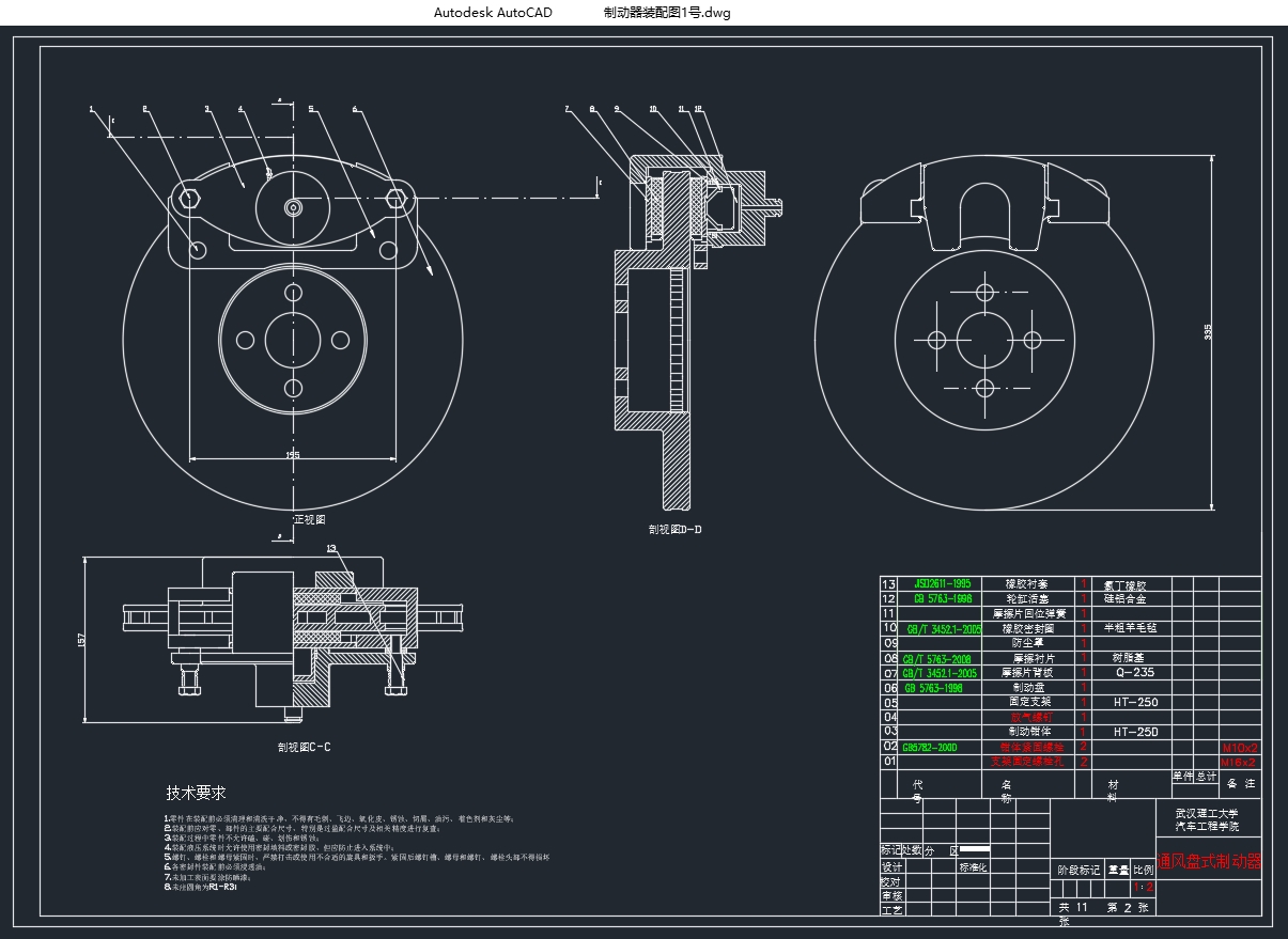
2.4 制动器方案选择 5
第3章 制动系统设计 8
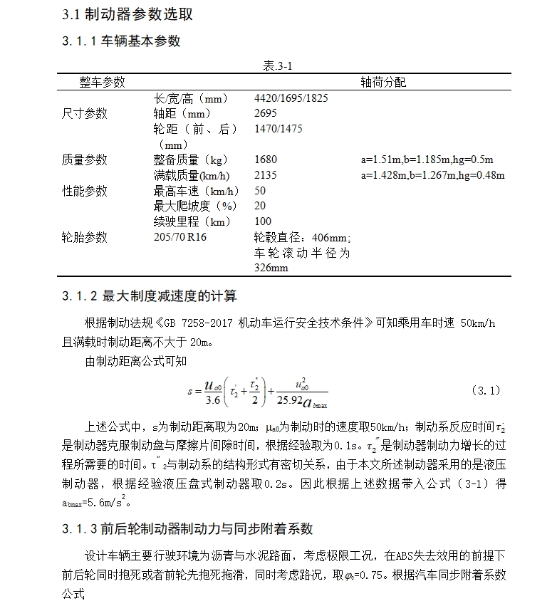
3.1制动器参数选取 8
3.1.1车辆基本参数 8
3.1.2 最大制度减速度的计算 8
3.1.3前后轮制动器制动力与同步附着系数 8
3.1.4制动力及制动力矩的计算 9
3.1.5盘式制动器主要参数计算 9
3.2制动器校核部分 11 [来源:http://www.doc163.com]
3.2.1制动衬片的磨损特性计算 11
3.2.2 驻车制动校核 12
3.2.3前后轮制动力矩的计算 12
第4章 无人驾驶制动驱动机构的计算 14
4.1制动驱动机构的形式 14
4.2制动主缸与制动轮缸设计计算 14
4.2.1制动轮缸直径d的计算 14
4.2.2制动主缸直径 14
4.3驱动电机的选择 15
4.3.1驱动电机功率的计算 15
4.3.2驱动电机的选择原则 16
4.4减速机构的设计计算 16
4.4.1蜗轮蜗杆的设计计算 16
4.4.2齿轮齿条的设计计算 17
4.4.3制动主缸推力的验证 18
4.5驱动减速机构壳体的设计 18
4.5.1减速机构的结构 18
4.5.2轴与轴承组合 19
4.5.3减速箱体的设计 19
4.5.4减速器附件设计 20
第5章 结论 22
5.1完成成果 22
5.2总结 22
5.3展望 22
参考文献 23
附录 24
致谢 29 [资料来源:Doc163.com]
上一篇:电动无人巴士转向系统的设计(含CAD零件图装配图,CATIA三维图)
下一篇:东风EQ1093中型汽车驱动桥设计(含CAD零件图装配图)