
1.6L乘用车前麦弗逊独立悬架设计(含CAD图,CATIA三维图)
1.6L乘用车前麦弗逊独立悬架设计(含CAD图,CATIA三维图)(任务书,开题报告,文献摘要,外文翻译,论文说明书12000字,CAD图7张,CATIA三维图)
摘要
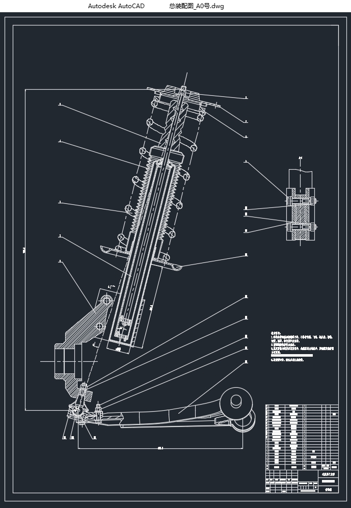
本次设计以1.6L自动版的大众朗逸为目标车型,对其前悬架进行设计计算,以满足车辆悬架系统对道路行驶及法律法规的要求。设计内容主要包括尺寸设计,三维建模及仿真运算。针对悬架的主要零件部分,即弹性元件,减振器,导向机构等,分别进行设计及强度校核;针对悬架的各零件,通过三维软件CATIA进行建模并完成装配;装配完成后对该悬架进行测量,获得硬点数据,再通过仿真软件ADAMS/CAR模块对该悬架进行仿真分析,以验证该悬架设计的合理性。
关键词:麦弗逊独立悬架;零件设计;CATIA三维建模;ADAMS仿真分析
Abstract
In this paper, a front Macpherson suspension is designed to meet the demands of law and road regulations. The design is targeting at a 1.6L Volkswagen Lavida car. The main process in this paper is to calculate the parts sizes, to build the 3D models and to do the suspension simulation. The main parts of the suspension, such as the spring, the bumper and the low control arm, will be designed and checked the strength. Then by using the CATIA software, the suspension is assembled, and the hard points of this suspension are measured. Using these hard points, the simulation on the suspension is conducted by ADAMS, and the results of the relationship between the wheel travel and the camber angle, caster angle, kingpin inclination angle and toe angle are obtained to verify the reasonableness of the design.
[资料来源:http://www.doc163.com]
Key words: Macpherson suspension;part design;CATIA modeling;ADAMS simulation
车型基本参数
本次设计选用的车型为1.6L自动版的大众朗逸,前悬架采用的是麦弗逊独立悬架,驱动方式为前置前驱,根据该车型说明书获得基本参数数据如表3.1所示。
表3.1 参数表
基本参数 数据
整车整备质量 1245kg
轴距 2610mm
空载总高 1465mm
满载总质量 1660kg
满载前轴荷质量 892kg
满载后轴荷质量 768kg
前轮轮距 1517mm
后轮轮距 1493mm
车轮直径 634.5mm
[资料来源:https://www.doc163.com]
 [资料来源:Doc163.com]
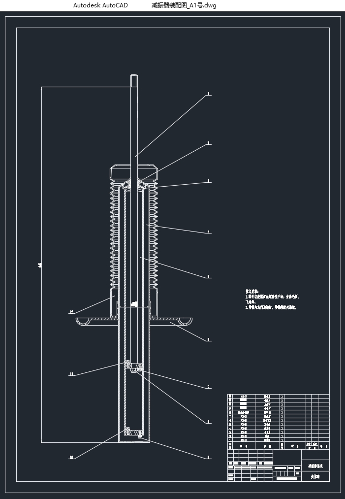


[资料来源:https://www.doc163.com]
目录
第1章 绪论 1
1.1 引言 1
1.1.1 课题研究背景和意义 1
1.1.2 国内外研究现状 1
1.2 课题研究内容、方法和目标 2
1.2.1 研究内容 2
1.2.2 研究方法 2
1.2.3 研究目标 3
第2章 麦弗逊独立悬架概述 4
2.1 悬架类型 4
2.2悬架设计要求 4
2.3悬架特点 5
第3章 麦弗逊独立悬架设计 6
3.1车型基本参数 6
3.2悬架主要参数的确定 6
3.2.1悬架频率的选择 6
3.2.2悬架的工作行程 7
3.2.3悬架的刚度 7
3.3螺旋弹簧的设计 8
3.3.1螺旋弹簧的刚度 8
3.3.2螺旋弹簧的基本参数选择及计算 9
3.3.3螺旋弹簧技术参数总结 12 [资料来源:http://Doc163.com]
3.4 悬架导向机构的设计 12
3.4.1对前轮独立悬架导向机构的要求 12
3.4.2导向机构的布置参数 13
3.4.3导向机构的受力分析 14
3.4.4摆臂轴线布置方式的选择 15
3.4.5摆臂长度的确定 16
3.4.6 悬架侧倾角刚度的计算 17
3.5减振器的设计 17
3.5.1减振器的选择 17
3.5.2相对阻尼系数ψ的选择 18
3.5.3减振器阻尼系数ψa的确定 18
3.5.4最大卸荷力F0的确定 19
3.5.5减振器主要尺寸的选择 19
3.5.6减振器主要技术参数总结 20
第4章 麦弗逊独立悬架零件三维建模 21
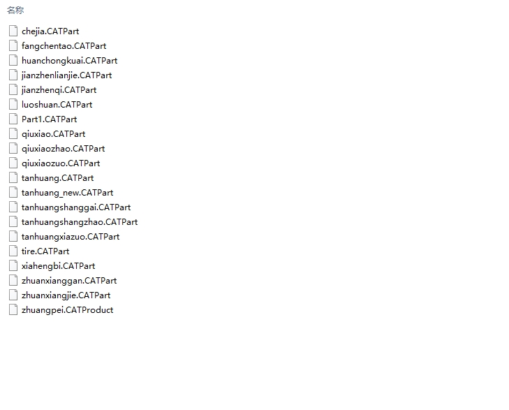
4.1螺旋弹簧建模 21
4.2筒式减振器建模 21
4.3导向机构建模 21
4.4其余零件 22
4.4.1转向节 22
4.4.2球销 22 [资料来源:http://Doc163.com]
4.4.3减振器连接件 23
4.4.4缓冲块 23
4.4.5防尘罩 24
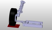
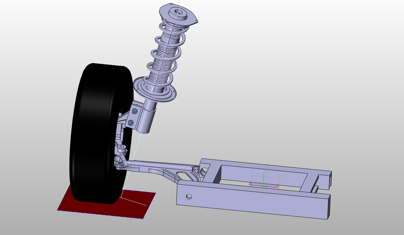
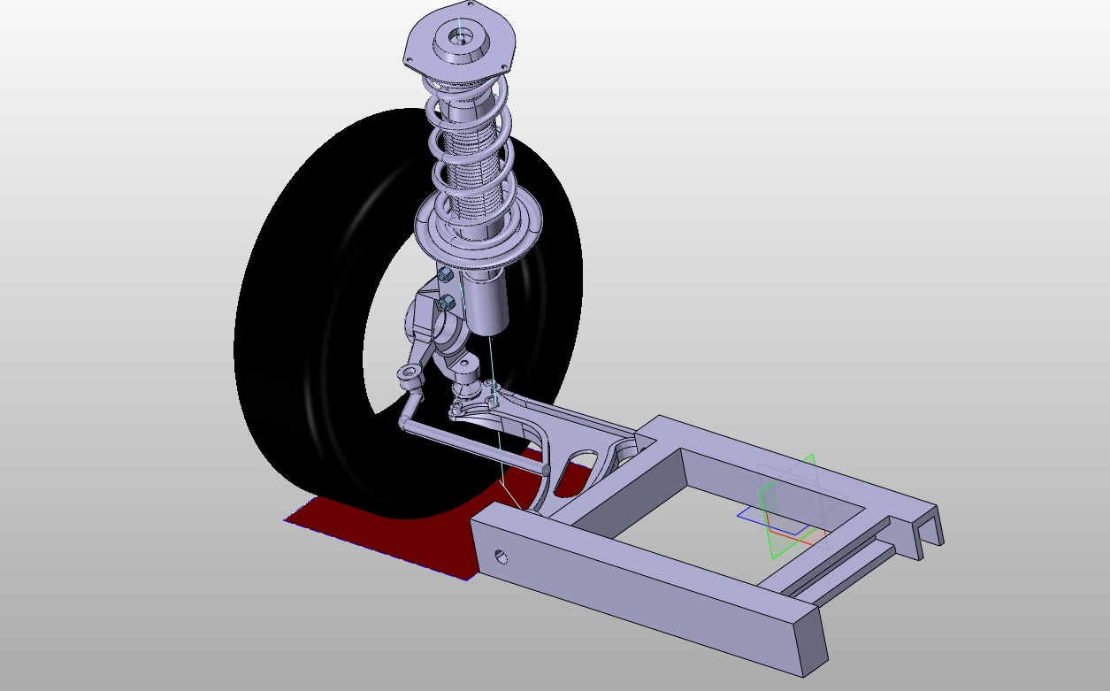
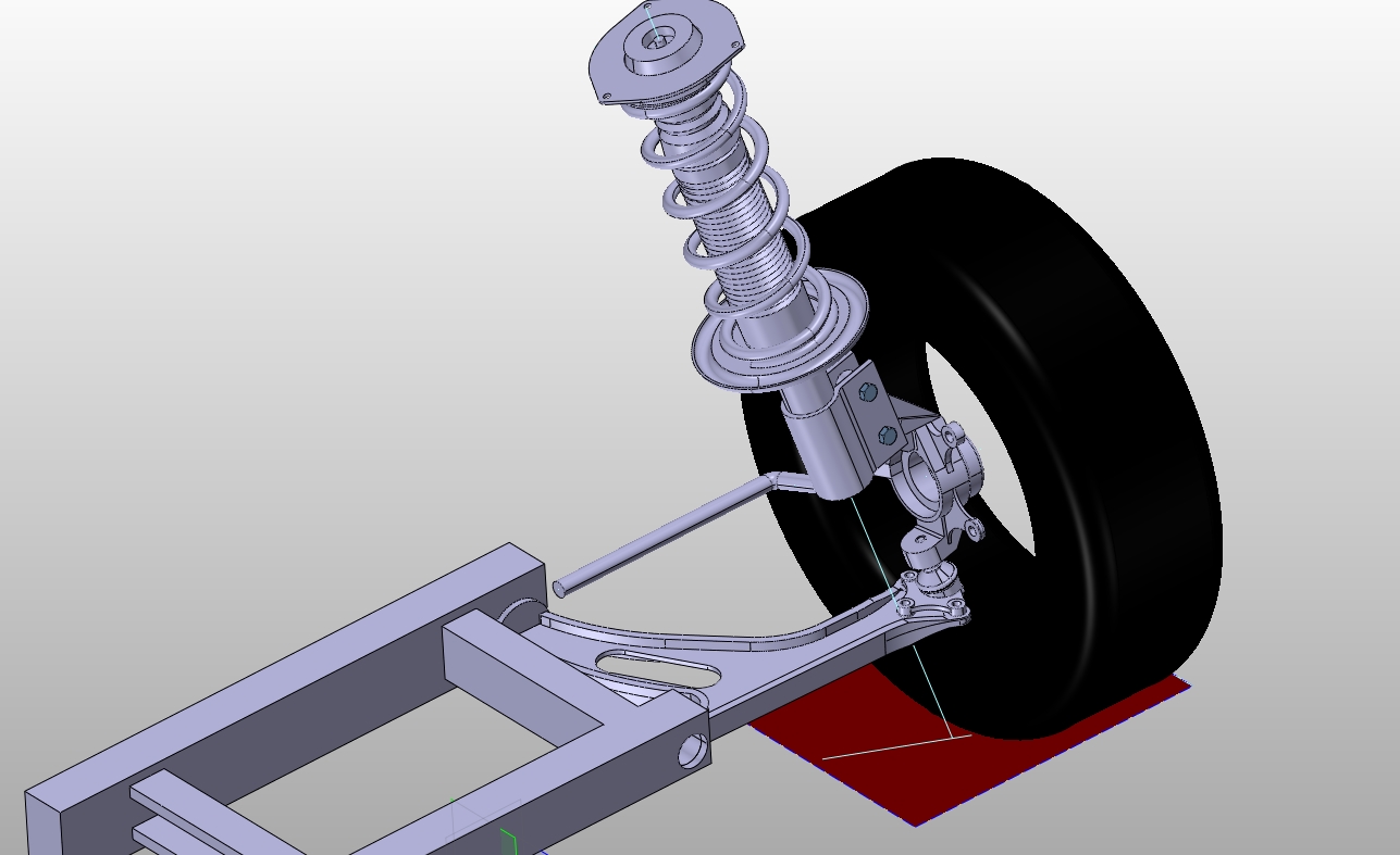
4.5悬架装配 24
第5章 麦弗逊悬架运动学仿真 27
5.1模型简化 27
5.2悬架参数设计 27
5.3悬架运动仿真 28
5.3.1 模型参数设置 28
5.3.2仿真结果分析 29
5.3.3悬架仿真分析小结 32
第6章 结论 33
参考文献 34
致谢 36
附录A 37 [资料来源:http://doc163.com]
上一篇:某车型前后盘式制动器设计及模态特性分析(含CAD图,CATIA三维图)
下一篇:智能应急指挥车的总体布置及设计(含CAD图,CATIA三维图