
6×6混合动力汽车行驶及驱动系统设计(含CAD图,CATIA三维图)
6×6混合动力汽车行驶及驱动系统设计(含CAD图,CATIA三维图)(任务书,开题报告,论文说明书20000字,CAD图6张,CATIA三维图)
摘要
随着生活日新月异的变化,汽车越来越多的出现在我们每个人的生活中,但是这也带来了一些问题,为了实现节约能源、减少排放的目的,汽车也在不断的发展。混合动力汽车因为其兼具电动汽车和燃油汽车的特点,既环保又能保证动力性,已成为未来汽车发展的重点。
本文以6×6分布式混合动力电动汽车为研究对象,根据设计参数已知车型为轻型车,因此参考全地形车的设计对该电动汽车进行行驶系统和驱动系统的设计。本文设计过程及主要内容如下:
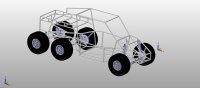
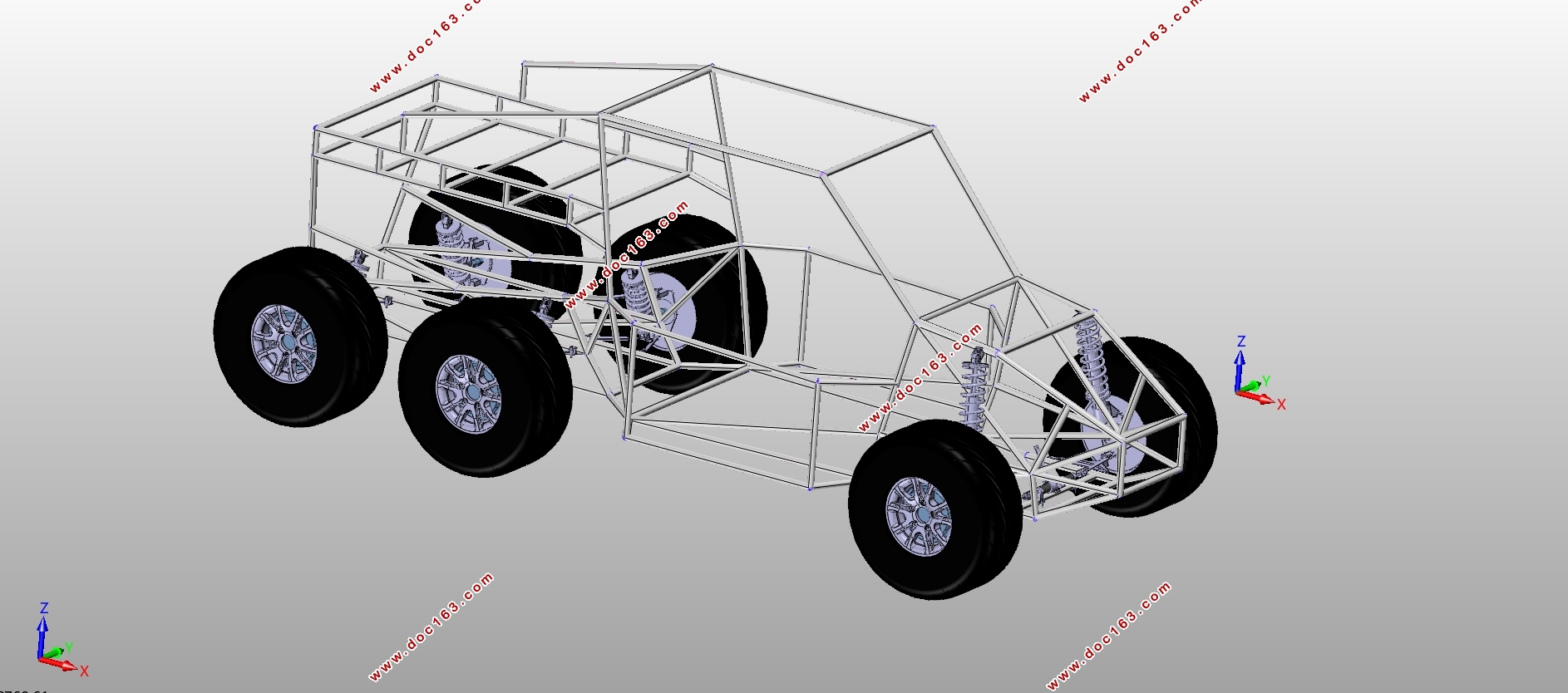
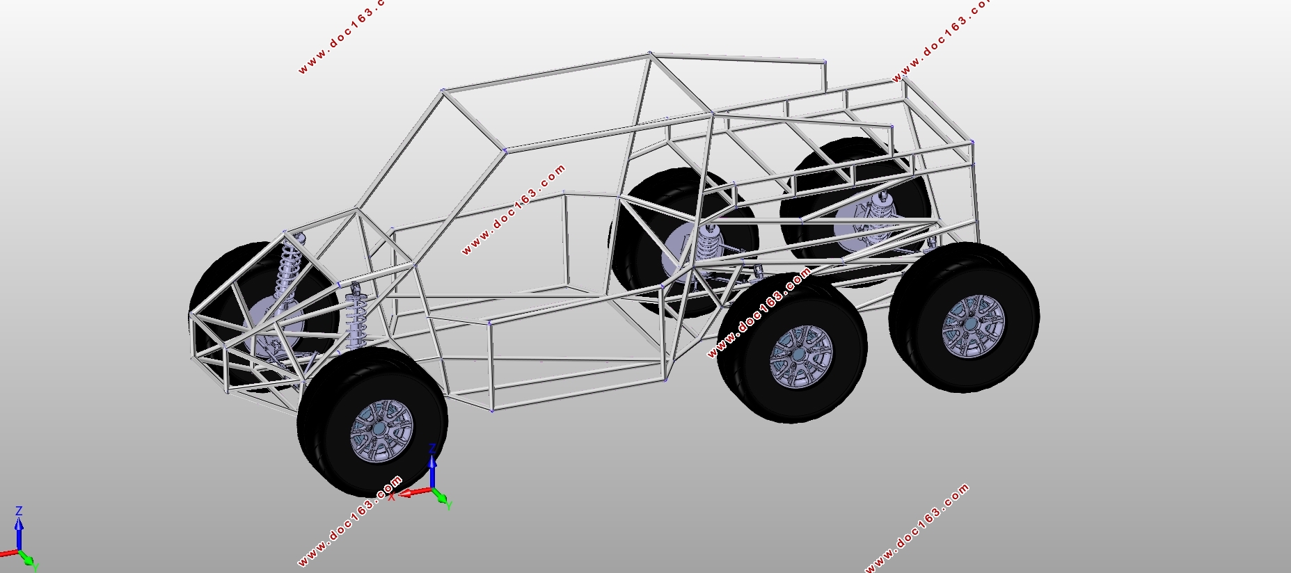
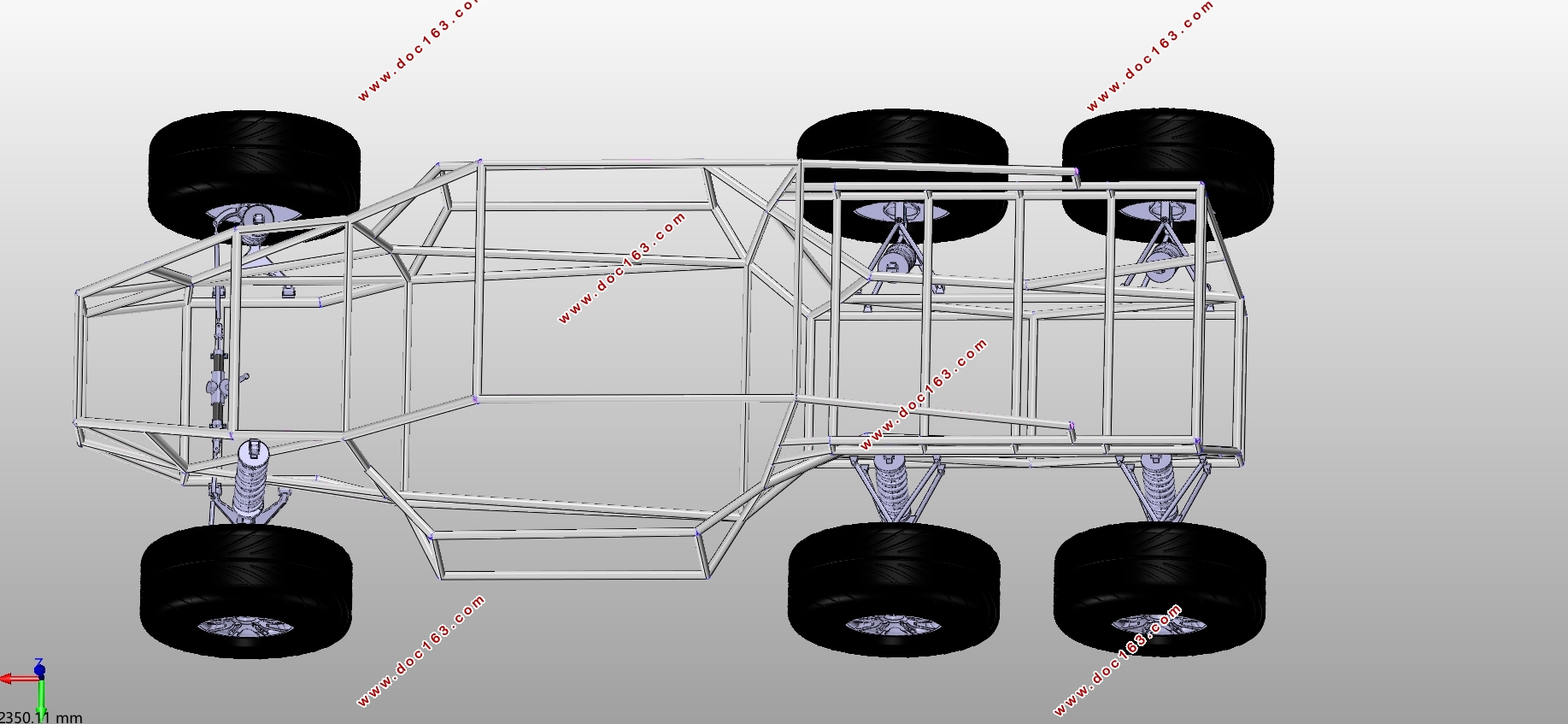
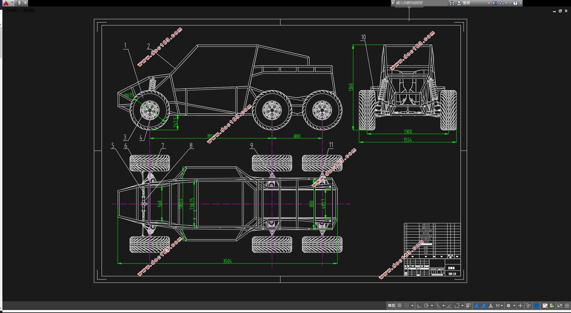
(1)首先,对该电动汽车的车架进行总体结构设计,根据参考车型确定整车参数,采用桁架式车架方案,利用钢管焊接组成车架,对车架进行结构设计,并运用CATIA软件建立三维模型;
(2)根据轮毂尺寸选定轮胎型号,建立轮胎模型;
(3)前悬采用麦弗逊悬架,后悬采用双横臂悬架;并进行相关的设计计算,包括螺旋弹簧的计算、减振器的设计与选型、导向机构的设计以及车轮定位参数的确定。本文详细阐述了前后悬架的设计过程,并对悬架建模,最后装配成行驶系总成模型。 [资料来源:Doc163.com]
(4)确定轮毂电机驱动方式,设计了一套运用单排圆柱行星齿轮传动的减速机构,其以2K-H型行星传动,减轻了质量和体积。运用于电动汽车上,充分体现了减速驱动电动轮技术的优势,并且满足整车动力性要求。
通过本次毕设的分析研究和计算,设计了一款6×6混合动力电动汽车的行驶系统总成,并在满足动力性要求下设计选型了一种带有行星齿轮系减速器的轮毂电机驱动系统。
关键词:混合动力;行驶系统;轮毂电机;行星齿轮传动;驱动系统
Abstract
With the rapid changes in life, more and more cars in the lives of each of us, but it also brings some problems, in order to achieve energy conservation, reduce emissions, the car is constantly evolving. Hybrid electric vehicles because of its both electric vehicles and fuel vehicles, both environmentally friendly and can ensure power, has become the focus of future car development.
In this paper, 6 × 6 distributed hybrid electric vehicle as the research object, according to the design parameters known models for the light vehicle, so the reference to the design of the whole terrain vehicle for the electric vehicle driving system and drive system design. The design process and the main contents are as follows:
(1)First of all, the overall structure of the electric car frame design, according to the reference model to determine vehicle parameters, the use of truss frame program, the use of steel pipe assembly frame, the frame structure design, and the use of CATIA software to establish three-dimensional model.
(2)Select the tire model based on the hub size to build the tire model.
(3)The front suspension with McPherson suspension, rear suspension with double wishbone suspension; and related design calculations, including the calculation of the coil spring, shock absorber design and selection, the design of the steering mechanism and the wheel positioning parameters to determine The This paper elaborates the design process of the front and rear suspension, and models the suspension, and finally assembles it into the driving line assembly model.
(4)A 2K-H planetary drive is designed to reduce the mass and volume, and it is used in electric vehicles to fully reflect the technology of decelerating drive electric wheel technology. It is designed to use a single row cylindrical planetary gear drive. Advantages, and to meet the vehicle power requirements.
Based on the analysis and calculation of this study, a 6 × 6 hybrid electric vehicle driving system assembly was designed, and a wheel with a planetary gear reducer was selected to meet the dynamic requirements. Motor drive system.
Key Words:Hybrid;Driving system;Wheel motor;Planetary gears;power system
[资料来源:https://www.doc163.com]

目录
第1章绪论 1
1.1 项目研究背景及意义 1
1.2 国内外的研究现状分析 2
1.2.1 国内研究现状 2
1.2.2 国外研究现状 2 [版权所有:http://DOC163.com]
1.3 本文主要的研究内容 4
第2章车轮与车架设计 5
2.1 行驶系统概述 5
2.2 车架的功用、设计要求及分类 5
2.2.1 车架概述 5
2.2.2 车架的类型 5
2.3 车架结构设计及建模 7
2.3.1 主要参数选择 7
2.3.2 车架设计与建模 7
2.4 车轮选型 10
第3章前悬架设计 11
3.1 悬架概述 11
3.2 悬架的各种结构型式 11
3.3 独立悬架的常见类型 12
3.3.1 双横臂式独立悬架 12
3.3.2 单纵臂式独立悬架 13
3.3.3 麦弗逊式独立悬架 13
3.4 前麦弗逊式独立悬架的设计计算 14
3.4.1 总体参数的确定 14
3.4.2 前轮定位参数的确定 14
3.5 弹性元件的设计计算 15
3.5.1 弹簧材料的选择 15
3.5.2 螺旋弹簧的设计计算 15
3.5.3 弹簧校核 17
3.5.4 弹簧其他尺寸计算 18
3.6 前悬架导向机构设计 19
3.6.1 前悬导向机构的设计要求 19
3.6.2 导向机构的参数设计 19
3.6.3 matlab中的悬架运动分析 21
3.7 减振器的设计计算 23
3.7.1 减振器的选型 23
3.7.2 相对阻尼系数ψ的确定 24
3.7.3 减振器阻尼系数δ的计算 24
3.7.4 最大卸荷力F0的计算 25
3.7.5 主要尺寸参数的计算 25
第4章后悬架设计 27
4.1 双横臂式悬架基本参数的确定 27
4.1.1 悬架静挠度fc 27
4.1.2 悬架动挠度fd 27
4.2 弹性元件的设计计算 27
4.2.1 弹簧材料的选择 27
[版权所有:http://DOC163.com]
4.2.2 弹簧刚度计算 27
4.2.3弹簧的设计计算及校核 28
4.2.4 弹簧其他尺寸计算 30
4.3 悬架导向机构设计 30
4.3.1 侧倾中心 30
4.3.2 纵向平面内上、下横臂轴的布置 31
4.4 后悬减振器设计 32
4.4.1 相对阻尼系数ψ的确定 32
4.4.2 减振器阻尼系数δ的计算 32
4.4.3 最大卸荷力F0的计算 33
4.4.4 减振器工作缸直径D 33
4.5 行驶系统总成 33
第5章轮毂电机驱动系统设计 35
5.1 轮毂电机驱动系统概述及方案选择 35
5.1.1 轮毂电机概述 35
5.1.2 轮毂电机驱动方式的选定 35
5.1.3 减速机构传动方案的选择 35
5.2 电机参数设计计算 36
5.2.1 整车性能参数 36
5.2.2 驱动电机参数计算 36 [资料来源:Doc163.com]
5.3 减速机构设计 38
5.3.1 行星齿轮传动中齿数分配应满足的条件 39
5.3.2 行星齿轮传动的配齿计算 40
5.3.3 行星齿轮参数设计 41
5.3.4 行星齿轮传动强度的校核计算 43
5.4 行星齿轮传动系的结构设计 44
5.4.1中心轮轴设计 44
5.4.2 行星轮支承结构设计 45
5.4.3 行星轮心轴的设计 45
5.4.4 行星架输出部分轴径设计 46
5.4.5 键连接设计 46
5.4.6 轴承的选择 47
第6章总结 48
参考文献 49
致谢 50
附录 51 [资料来源:Doc163.com]
上一篇:轻型客车悬架系统匹配计算及板簧和减振器总成设计(含CAD图,CATIA三维图)
下一篇:东风猛士EQ2050B的驱动桥设计(含CAD零件图装配图,CATIA三维图)