
基于单片机的点滴输液控制系统的设计
基于单片机的点滴输液控制系统的设计(开题报告,论文13800字)
摘 要
随着科学技术的日新月异,越来越的高科技产品逐步贴近人类的生活,众所周知,医疗事业始终需要跟着科技的发展,而科技发展的产物也需要被很好的利用在医疗事业中。
本设计采用的是当下比较普及的STC89C52单片机,从站以H桥型步进电机驱动电路来控制输液滴速,键盘来设置运行状态以及速度、误差值,LED数码管显示,红外对射管采集数据,声光报警器进行声光报警灯,从站与主站之间亦可通信,主站能很好的观测到从站的号码以及当前从站的速度值,从站液位低于警戒线报警后,主站亦会发出警报。本设计结构简单,成本低廉,适于普及。
关键字:单片机;驱动;键盘;声光报警
The design of the liquid inputting system basing on one-chip computer
Abstract
With advances in science and technology, more and more high-tech products gradually close to human life, it is well known that the medical enterprise always need to follow the development of science and technology, and the product of the development of science and technology also needs to be good use in the medical enterprise. [来源:http://www.doc163.com]
This design USES the more popular at the present time the STC89C52 single-chip microcomputer, from the stand to H bridge stepper motor driver circuit to control the infusion dripping speed, the keyboard to set the running state and speed, the error value, LED digital tube display, infrared correlation data, sound and light alarm with sound and light alarm lamp, from the stand and can communication between master station, master station can be a very good observed from the station number and the current value from the station, the station level below the line after the alarm, the main also sounded the alarm. This design has simple structure, low cost, the operation is not trival, and it is suitable for popularization.
Key words:one-chip computer;drive;keyboard;Sound and light alarm
[资料来源:http://Doc163.com]
目 录
摘 要 I
Abstract II
第一章 绪论 2
1.1 输液控制系统的设计背景 2
1.2 输液控制系统的发展与前景 2
1.3 输液控制系统的设计 4
第二章 设计要求和方案论证 4 [资料来源:https://www.doc163.com]
2.1 设计要求 4
2.2 系统设计方案及其论证 4
2.2.1 单片机型号的选择 4
2.2.2 显示模块方案的选择 4
2.2.3 滴速传感器方案的选取 4
2.2.4 液位传感器方案的选择 6
2.2.5 电机控制方案的选择 7
2.2.6 蜂鸣器的选择 8
2.2.7 主从站协议部分 8
2.2.8 电路设计的最终方案 8
第三章 硬件设计 9
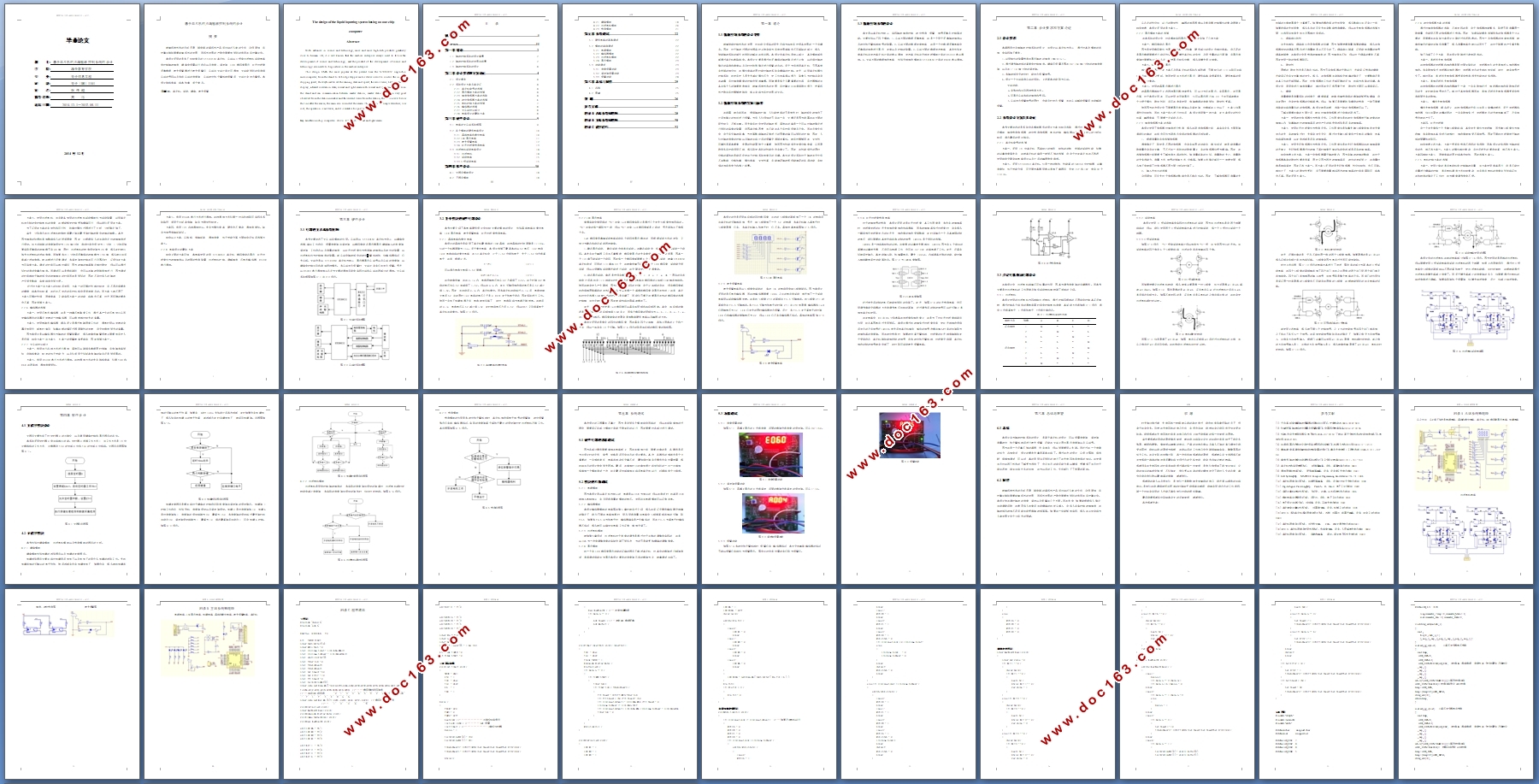
3.1 电路的主从站系统框图 9
3.2 各个模块的硬件电路设计 10
3.2.1 晶振电路和复位电路 10
3.2.2 LED显示电路 11
3.2.3 声光报警电路 12
3.3.4 红外对射管检测电路 13
3.3 步进电机驱动电路设计 14
3.3.1 步进电机 14
3.3.2 驱动电路 15
3.3.3 H桥驱动电路 15 [版权所有:http://DOC163.com]
第四章 软件设计 18
4.1 主程序模块设计 18
4.2 子程序模块 18
4.2.1 键盘模块 18
4.2.2 步进电机模块 20
4.2.3 检测模块 21
第五章 系统调试 22
5.1 硬件电路的基本调试 22
5.2 模块的单独调试 22
5.2.1 电源模块 22
5.2.2 蜂鸣器模块 22
5.2.3 步进电机模块 22
5.2.4 显示模块 23
5.3 功能调试 23
5.3.1 速度设置功能 23
5.3.2 误差值设置功能 23
5.3.3 报警功能 24
第六章 总结与展望 25
6.1 总结 25
6.2 展望 25
致 谢 26
参考文献 27
附录A 从站系统原理图 28
附录B 主站系统原理图 30 [来源:http://www.doc163.com]
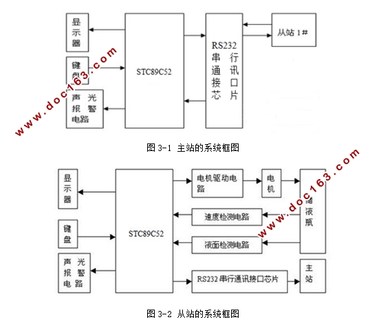
附录C 程序清单 32