
基于单片机的环境参数监测系统设计(附电路原理图)
基于单片机的环境参数监测系统设计(附电路原理图)(任务书,开题报告,论文11000字)
摘要
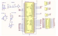
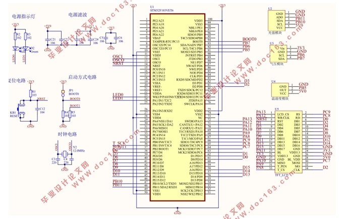
环境参数是现在各行各业生产中都特别重视的一部分,对各项环境参数的检测是必不可少的。利用传感器监测环境中的温度、湿度、光照强度和空气压强有着高精度、简单便捷、成本低的优点,适合广泛的推广普及到各行各业中。传统的环境参数检测方法由于受到环境变化的影响容易产生较大的误差,已经不适用于当前的需求和标准了。本次系统是以STM32F103ZET6位主控芯片,外接三个传感器,分别是温湿度传感器、光照强度传感器和空气压强传感器,作为采集环境参数信号的装置。传感器对信号的采集,放大信号之后通过滤波电路,最后在到STM32单片机上进行信号处理,最后将处理的信号数据显示在LCD显示屏上面。此次系统经过多次测试以后得出能够比较精准的检测出以上环境参数。
关键词:环境参数 检测系统 传感器
Environment parameter monitoring system based on single chip microcomputer
Abstract
The environmental parameters is now part of production in all walks of life are paying special attention to the detection of various environmental parameters. It is necessary to use sensors to monitor the environmental temperature, humidity, light intensity and air pressure with high precision, simple and convenient, low cost, suitable for wide popularization in all walks of life. The detection method the traditional environmental parameters influenced by environmental change prone to large errors and is not suitable for the current needs and standards. This system is based on STM32F103ZET6 control chip, outside the three sensors, which are temperature and humidity sensor, light intensity sensor and The air pressure sensor, as the device parameters of signal acquisition environment. Sensor signal acquisition, amplification signal through the filter circuit, and finally in the signal processing to the STM32 microcontroller, the signal processing of the final data will be displayed on the LCD screen above. The system tested many times obtains more accurate detection of the above parameters. [来源:http://Doc163.com]
Key Words: Environmental parameters; detection system; sensor
[资料来源:http://doc163.com]
目录
摘要 I
Abstract II
第一章 绪论 1
1.1 引言 1
1.2 研究背景与意义 2
1.3 国内外研究现状 3
1.4 论文研究的目的及内容 4
1.5 论文结构 5
第二章 系统的总体设计方案 6
2.1 系统设计思路 6
2.2 系统总体框架 6
2.3 主要模块的方案选择 7
2.3.1 主控芯片 7
2.3.2 传感器模块 9
2.3.3 液晶显示模块 13
第三章 系统软件设计与实现 15
3.1 软件主流程 15
3.2 传感器程序设计 16 [资料来源:http://doc163.com]
3.2.1 光照传感器BH1750FVI 模块 16
3.2.2 GY-68 BMP180温度 气压传感器模块 17
3.2.3 单总线数字温湿度传感器 DHT11模块 18
3.3 LCD液晶显示屏 22
第四章 系统的调试 28
4.1 硬件调试 28
4.1.1 各个传感器的检测 28
4.1.2 主控模块 29
4.2 软件调试 29
4.3 调试结果 30
4.3.1 测试实现结果 30
4.3.2 调试结论 31
第五章 结论与展望 32
5.1 结论与展望 32
5.2 下一步的工作 33
参考文献 34
致谢 36
系统原理图 37
[来源:http://www.doc163.com]