
常州XX花苑商住楼给水排水工程设计(含CAD图)
常州XX花苑商住楼给水排水工程设计(含CAD图)(任务书,开题报告,外文翻译,计算说明书14000字,CAD图纸24张)
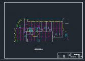
常州XX花苑商住楼主体建筑为地上二十八层,地下一层。地下一层为车库,地上一至二层为商铺,每层建筑面积1200m²,三至二十八层为住宅,每层建筑面积约570m²。
市政自来水压力约为: 0.25MPa。
给水系统:生活给水系统分成三区,一区地下室~2层由市政管网直接供水,二区3~16层由变频水泵1给水系统供水,三区17~28层有变频水泵2给水系统供水。
排水系统:采用传统排水的方案,卫生间污废水合流.采用UPVC螺旋消音排水立管排水,采用传统的排水方式即各卫生器具穿越楼板进入下层的排水方式,各管设伸顶通气管通气,各排水干管在地下层汇合至一根管排出。地下室废水经集水坑收集、潜污泵(固定自耦式安装)提升后排出。建筑物污水汇集经化粪池处理后排入城市管网集中送至城区集中污水处理厂
本花苑的屋面雨水及阳台雨水均单独设立管排放,另有空调冷凝水及空调机隔板雨水也经收集后统一排放。
消防给水系统:室外消防贮水池贮备2小时消防栓给水用水量和1小时自动喷淋灭火系统用水量.屋顶消防水箱提供火灾前10分钟用水。
自动喷淋系统:本建筑总的布置喷头数未超过800个,根据规范要求,一个湿式水力报警阀最多可接800个喷头。因此本建筑只需要设一个水力报警阀。
该建筑采用湿式自动喷水灭火系统,报警阀设于地下室设备间,各层均设水流指示器和信号阀,其信号均送到一楼消防控制中心进行处理。
该建筑各层均设自动喷水系统,其动作喷头为68°C,本建筑防火等级为中危险级,其喷头间距为3.6 ×3.6m,呈正方形布置。距墙不大于1.8m。为定期进行安全检查,各层均设末段试压装置,废水排进泄水管。为加强供水在室外设有两个水泵接合器。
Changzhou Rose Garden commercial building the main building is twenty-eight floors on the ground, the underground layer. Underground garage, the ground to two for shops, the building area of each floor 1200m ², three to twenty-eight storeys for residential, each floor area of about 570m ².
The municipal tap water pressure is about: 0.25MPa.
Water supply system: life water system is divided into three zones, the basement area ~2 layer directly by the municipal pipe network of water supply, two 3~16 water layer composed of variable frequency pump 1 water supply system, 17~28 has three areas of frequency pump water 2 water supply system.
Drainage system: the traditional drainage schemes, toilet sewage waste hydrated flow. Using UPVC spiral muffling drain stand pipe drainage, the drainage way traditional drainage system is the sanitary appliances through the floor into the lower, the pipe is provided with ventilating pipe ventilation, the drainage pipe discharge in the lower convergence to a root canal. The basement of wastewater through sump collection, sewage submersible pump (fixed autotransformer type installation) lifting after discharge. Building sewage collection is treated in the septic tank is discharged into the city pipe network concentrated to urban centralized sewage treatment plant
The garden balcony roof rainwater and rainwater are separate pipe emissions, and air-conditioning condensation water and air conditioner separator rain after collection uniform emission.
Fire water supply system: outdoor fire water storage tank standby 2 hours of fire hydrant water use and 1 hours of automatic sprinkler system water. Water tank in the roof to provide fire 10 minutes before the water.
[资料来源:www.doc163.com]
Automatic sprinkler system: the architectural layout of nozzle total number of not more than 800, according to the specification requirements, a wet hydraulic alarm valve most can be connected 800 nozzle. This architecture requires only a hydraulic alarm valve.
The building adopts wet automatic sprinkler system, alarm valve is arranged on the basement equipment, each layer is provided with flow indicator and signal valve, the signals are sent to a building fire control center processing.
The construction of each layer are equipped with automatic sprinkler system, the nozzle with 68 ° C, grade of the building for fire danger level, the nozzle spacing is 3.6 × 3.6m, a square layout. Away from the wall is not more than 1.8m. To conduct regular safety inspections, each layer set terminal pressure test device, waste water discharged into the drain pipe. In order to strengthen water supply two pump adapter is arranged in the outdoor
[资料来源:www.doc163.com]


[资料来源:https://www.doc163.com]
目 录
摘要…………………………………………………………………………………I
ABSTRACT………………………………………………………………………II
第一章 设计说明…………………………………………………………………1
1.1 给水工程……………………………………………………………………1
1.1.1 给水系统的选择……………………………………………………1
1.1.2 系统的组成…………………………………………………………1
1.1.3 加压设备及构筑物…………………………………………………1
1.1.4 管道布置及设备安装要求…………………………………………1
1.2 排水工程……………………………………………………………………2
1.2.1 系统选择……………………………………………………………2
1.2.2 系统组成……………………………………………………………2
1.2.3 主要设备及构筑物…………………………………………………2
1.2.4 排水管道安装要求…………………………………………………2
1.3 消防给水……………………………………………………………………4
1.3.1 室内消火栓系统……………………………………………………4
1.3.1.1 室内消火栓系统的选择……………………………………4
[资料来源:www.doc163.com]
1.3.1.2 系统组成:…………………………………………………4
1.3.1.3 设备及构筑物:……………………………………………4
1.3.2 自动喷淋系统………………………………………………………4
1.3.2.1 室内自动喷水灭火系统的选择……………………………4
1.3.2.2 系统组成……………………………………………………5
1.3.2.3 设备及构筑物………………………………………………5
1.3.3 消防管道及设备安装要求…………………………………………5
1.3.3.1 消火栓的安装………………………………………………5
1.3.3.2 自动喷淋的管道安装………………………………………5
第二章 设计计算…………………………………………………………………6
2.1 室内给水系统计算…………………………………………………………6
2.1.1 给水用水定额及时变化系数………………………………………6 [资料来源:http://Doc163.com]
2.1.2 最高日用水…………………………………………………………6
2.1.3 最高日最大时用水量………………………………………………6
2.1.4 设计秒流量…………………………………………………………6
2.1.5 生活水箱容积………………………………………………………6
2.1.6 室内管网压力………………………………………………………7
2.1.7 选泵 ………………………………………………………………10
[来源:http://www.doc163.com]
2.2 室内排水系统计算…………………………………………………………10
2.2.1 一层卫生间排水计算………………………………………………10
2.2.2 二层卫生间排水计算………………………………………………10
2.2.3 标准层卫生间排水计算……………………………………………13
2.2.4 标准层厨房排水计算………………………………………………14
2.2.5 地下室排水…………………………………………………………14
[资料来源:http://Doc163.com]
2.2.6 化粪池………………………………………………………………14
2.3 消火栓系统计算……………………………………………………………19
2.3.1 消火栓的布置………………………………………………………19
2.3.2 水枪喷嘴处所需水压………………………………………………19
2.3.3 水枪喷嘴的出流量…………………………………………………19
2.3.4 水带阻力……………………………………………………………19
[资料来源:https://www.doc163.com]
2.3.5 消火栓口所需的水压………………………………………………19
2.3.6 校核…………………………………………………………………19
2.3.7 水力计算……………………………………………………………21
2.3.8 减压…………………………………………………………………21
2.3.9 消防水箱……………………………………………………………21
2.3.10消防贮水池…………………………………………………………22
2.4 室内喷淋系统计算…………………………………………………………22
2.4.1 喷淋布置……………………………………………………………22
2.4.2 标层喷淋计算………………………………………………………22
2.4.3 二层商业区喷淋计算………………………………………………23
2.4.4 立管计算……………………………………………………………27 [资料来源:http://www.doc163.com]
2.4.5 减压…………………………………………………………………28
2.4.6 报警阀及喷头………………………………………………………28
2.4.7 水泵结合器…………………………………………………………28
参考文献…………………………………………………………………………30
结语………………………………………………………………………………31 [来源:http://www.doc163.com]
致谢………………………………………………………………………………32