
磁悬浮轨道廊式接驳系统设计(含CAD图,SolidWorks三维图)

磁悬浮轨道廊式接驳系统设计(含CAD图,SolidWorks三维图)(任务书,开题报告,外文翻译,论文说明书10000字,周记,CAD图5张,SolidWorks三维图)
摘要
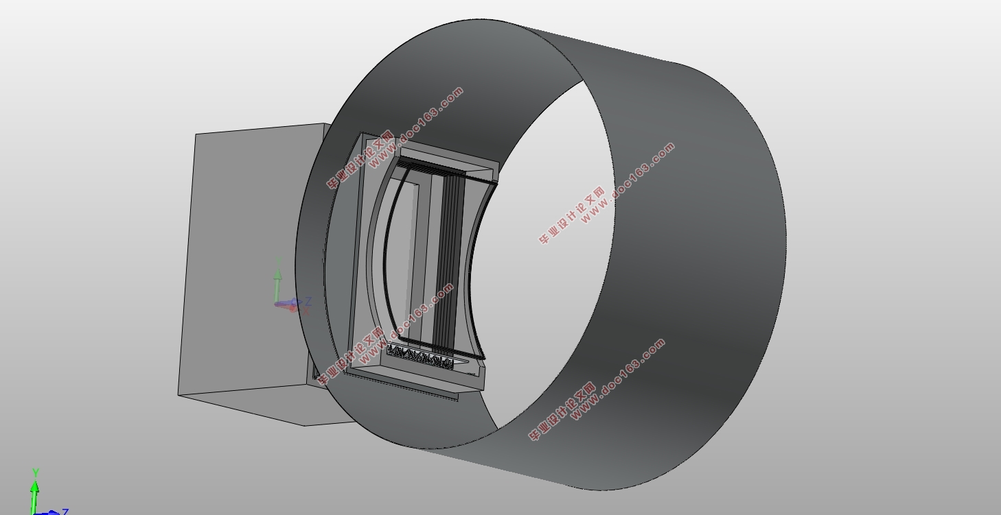
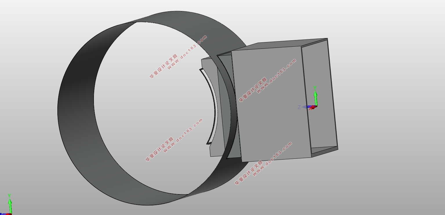
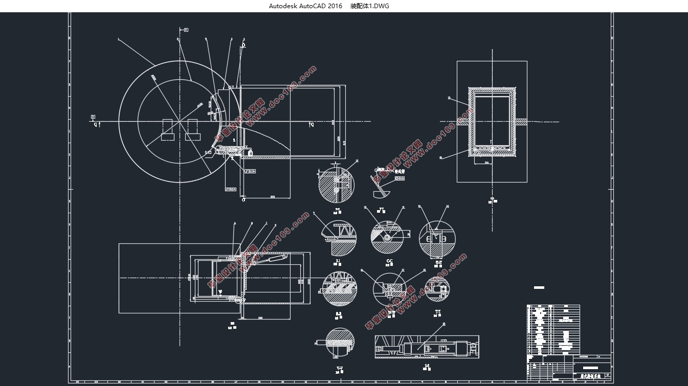
真空密封的采用方形站台(2770mm×1820mm×500mm)内置可移动内廊(2400mm×1500mm×877mm)采用4.2kw的电动缸,其行程设置为200mm。其中内廊的壁厚为10mm廊道长为870mm,通过定位在门下的电动缸(电动缸功率为4.2kw)驱动移动廊进行伸缩运动。移动内廊与站台之间的缝隙通过J形密封圈进行密封,密封圈一边固定在站台部分,另一部分通过压板固定在站台内部,另一端与移动内廊道紧贴,密封圈与内廊之间通过油润滑。车身与廊道之间通过T形密封带进行密封。密封带与移动廊道配合车身形状进行密封。廊道通过三个导轨对于内廊进行定位与支撑。导轨位于廊道接口的下部。廊道后处使用可安装的导轮,与滑轨的位置对齐,通过电动缸进行驱动。
关键字:真空密封;电动缸;导轨;
abstract
Vacuum sealed square platform (2770mm × 1820mm × 500mm) built-in mobile interior corridor (2400mm × 1500mm × 877mm) 4.2kW electric cylinder, the stroke is set to 200mm. The wall thickness of the inner corridor is 10mm and the length of the corridor is 870mm. The electric corridor (electric cylinder power is 4.2kw) located under the door drives the mobile corridor for telescopic movement. The gap between the mobile interior gallery and the platform is sealed by a J-shaped sealing ring. One side of the sealing ring is fixed on the platform part, the other part is fixed inside the platform through a pressure plate, and the other end is closely attached to the moving inner gallery, and the sealing ring and the inner gallery are Oil lubrication between rooms. The body and the corridor are sealed by a T-shaped sealing tape. The sealing tape and the mobile corridor are sealed together with the body shape. The galleries locate and support the galleries through three guide rails. The guide rails are located in the lower part of the corridor interface. Use a mountable guide wheel behind the corridor to align with the slide rails. [版权所有:http://DOC163.com]
Key words: Vacuum seal; Electric cylinder;Guide;
[资料来源:http://www.doc163.com]

 [资料来源:https://www.doc163.com]
目录
摘要 1
abstract 1
1.绪论 1
1.1国外现状 1
1.2国内现状 3
1.2研究目的及意义 3
1.3设计初稿 4
2方案设计 4
2.1方案选择 5
2.2方案介绍 7
2.2.1支撑方式 7
2.2.2 驱动方式 7
2.2.3密封方式 8
3 实体设计 9
3.1车身-内廊密封带 9
3.2 廊道-站台密封圈 10
3.3 管道门设计 11
3.4真空泵的设计选型 13
3.4.1真空泵的选型 13
3.5动力驱动 14
3.6 管道-廊道 14
4总结与展望 14
5参考文献 15
下一篇:7500t/h装船机总体设计及回转机构设计(含CAD零件图装配图)